| Home | About Us | Products | Tech Papers | Contact Us |
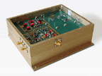
Clock generators Clock generators are used as system clocks in applications such as DDS based synthesizers.
The approach we use is multiplying standard high-quality references by a suitable number and filtering out unwanted signals, and subsequently
amplifying it to attain the desired level.
Our standard model, AUM-0001-CGK, accepts a 10 MHz input and delivers 50, 200, and 400 MHz sin wave
outputs, with typical phase noise degradation of 20 log N +3 dB. Please contact us regarding other outputs (ECL, TTL, LVPECL, and LVNECL) and
frequency requirements. Our internal reference module measures 5 x 4.5 x 1.75 in. Our external reference module measures 5 x 4.5 x 1 in.
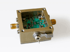
Down converters are used to convert high-frequency signals into more manageable low-frequency signals for further baseband processing.
Our standard model, AUM-0001-DCK, consists of low noise amplifiers, two stages of frequency converters, and appropriate filters. It converts a 950-1750 MHz signal into a fixed 60 MHz IF signal, with 20 dB gain and 16 dB noise figure. This module accepts inputs of -90 dBm to -60 dBm, and is available in a 20 KHz step-size. Other IF frequencies and step sizes are available upon request.
This module
measures 2 x 2 x 1 in.
Low-noise amplifiers (narrow-band and wide-band)
Low-noise amplifiers
((LNAs) are used in receivers where weak signals are detected with
minimal distortion. LNAs are also useful in frequency multiplier
chains where the amplifier contributes minimally to the overall
phase noise of the system.

Our standard model AUM-0001-AK covers a frequency band of 50-1200 MHz with a 35 dB gain and gain variation not exceeding ± 1 dB. The typical noise figure is 2.5 dB across the band with input and output VSWR 1.3:1 typical. 1 dB compression point for this model is better than +13 dBm.
This module measures 1.25 x 1.25 x .76 in. Its operating temperature range is
-30° to +70°C.
L-band, C-band, & Ka-band converters
Our L-band, C-band & Ka-band converters are mainly used in satellite communication to translate signals from one band of frequencies to another. During this translation stage, the signal distortion should be kept to a minimum. We achieve this goal by making use of our low-noise components: signal sources, amplifiers, and mixers.
Our 720 MHz to L-band converter translates a 720 MHz signal into two or more frequency channels in the L-band starting from 1000 to 1400 MHz, with a conversion loss of 0 dB and noise figure not exceeding 16 dB. Our signal sources used in frequency translation have a typical phase noise of better than -110 dB at 10 KHz offset.
Our 720 MHz to C-band converter translates a 720 MHz signal into two or more frequency channels in the C-band starting from 5.5 to 5.9 GHz, with a conversion loss of 0 dB and noise figure not exceeding 16 dB. Our signal sources used in frequency translation have a typical phase noise of better than -110 dB at 10 KHz offset.
Our Ka-band block converter converts C-band signals into Ka-band signals by using signal sources of phase noise better than -107 dBc/Hz at 10 KHz offset.
The sizes of our converters vary depending on customer requirements.
Test fixtures Our text fixtures can be broadly classified into two categories: low-frequency and high-frequency.
Engineers use test fixtures to evaluate components, sub-systems, and systems before they are incorporated into an end product. Our test fixtures can be as simple
as those needed to test a single device such as a crystal oscillator and as complex as those needed to test a satellite-bound transceiver. Simple fixtures are easy
to implement at a relatively low cost. We specialize in designing and manufacturing complicated test fixtures including: The sizes of our test fixtures vary depending on customer requirements.
Copyright © 2005 AUM Technology. All rights reserved.